
2025
2(82)
Milan Sýkora*, Paweł Konczewski**, Radosław Biel***
Ronow Castle in Trzciniec – interdisciplinary research
on a medieval stronghold at the Czech-Lusatian borderland
DOI: 10.37190/arc250202
Published in open access. CC BY NC ND license
Abstract
The Ronow Castle in Trzciniec near Bogatynia, associated with the noble Ronovci family, served as a key political and military centre in the region
from the 13
th
to the 15
th
century, yet it remains poorly studied in Polish scholarly literature.
This article presents the results of interdisciplinary research conducted in 2022. The scope of the study included archival research, critical analysis
of previous studies, and examination of architectural remains and landscape features. The research combined traditional historical methods with mod-
ern spatial documentation techniques (ground-based photogrammetry and airborne LiDAR scanning).
The study led to the functional division of the castle complex into four zones: the outer ward, outer fortications, bailey, and main castle. Evidence
of the site’s multi-phase development was conrmed, including remnants of defensive walls, communication systems, and cellars. In addition, new
architectural elements were identied, such as a two-storey building located in the uncellared part of the castle. The ndings also allowed for the veri-
cation of some earlier hypotheses, particularly concerning the construction of the outer defences and the supposed existence of a transverse wall with
a projecting tower beyond the bailey. However, the precise chronological stratication of the complex remains unresolved. The article highlights the
need for further research, particularly through geophysical and archaeological methods, to achieve a more comprehensive reconstruction of the history
and architecture of Ronow Castle.
Key words: LiDAR, Middle Ages, castellology, Upper Lusatia, Ronow castle
Introduction
Ronow Castle (German: Rhonaw), located in Trzciniec
near Bogatynia, is a medieval stronghold situated at the
intersection of today’s borders of Poland, Germany, and
the Czech Republic. Its historical development reects
the political transformations of Central Europe, particu-
larly within the region of Upper Lusatia. Interdisciplinary
studies of the site focus both on its architectural remains
and the broader landscape context (Lehký, Sýkora 2014;
Boguszewicz 2010; Chorowska 2003). The advancement
of castle studies today is supported by digital, non-inva-
sive techniques that enable the creation of detailed spatial
documentation (Guth 2018). This article aims to present
the historical background of Ronow, outline the property’s
ownership changes from the 13
th
to the 15
th
century, and
discuss the results of architectural surveys and analytical
work carried out to date.
State of research
Research on Ronow Castle began as early as the 18
th
century. The rst known description of the ruins was pro-
vided by Johann Benedict Carpzov in 1716 in his Annalec-
ta Fastorum Zittaviensium. He noted the castle’s location,
the condition of the preserved walls and cellars, and the
parcelling of the lower ward. His account also included
documents concerning the castle’s owners, although it con-
tained errors typical of the period. These included reliance
on secondary or chancery sources, many of which are un-
veriable today, as well as elements of a romanticised vi-
sion of the castle’s siege.
* ORCID: 0009-0001-3284-0544. Institute for Preservation of
Archaeological Heritage of Northwest Bohemia, Czech Republic.
** ORCID: 0000-0002-6326-8181. Faculty of Biology and Ani-
mal Science, Wrocław University of Environmental and Life Sciences,
Poland.
*** ORCID: 0000-0002-1505-1279. Faculty of Biology and Ani-
mal Science, Wrocław University of Environmental and Life Sciences,
Poland, e-mail: radoslaw.biel@upwr.edu.pl
16 Milan Sýkora, Paweł Konczewski, Radosław Biel
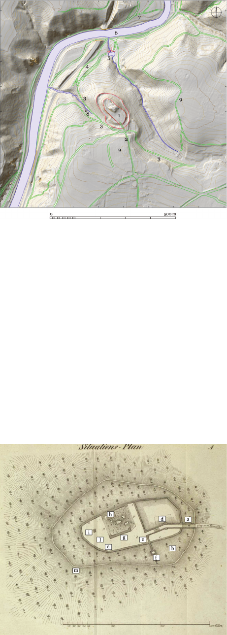
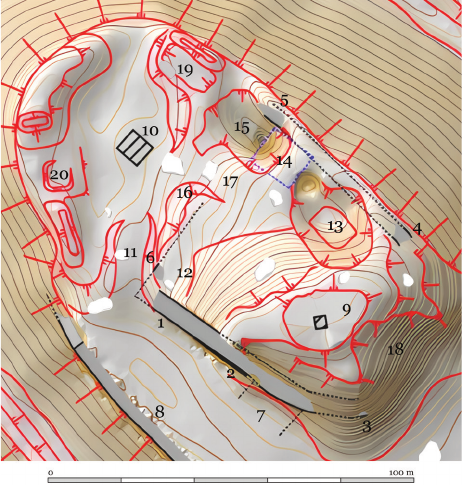
Fig. 1. Plan of the broader surroundings of the castle:
1 – castle, 2 – main access road,
3 – additional medieval road,
4 – ravines, 5 – dam of the smaller pond,
6 – ford on the Lusatian Neisse River,
7 – roads ascending to the north-east,
8 – well in the western valley,
9 – two proposed locations of the 1399 siege camp
(elaborated by P. Hlavenka, M. Sýkora, J. Vidman)
Il. 1. Plan szerszego otoczenia zamku:
1 – zamek, 2 – główna droga dojazdowa,
3 – dodatkowa droga średniowieczna, 4 – wąwozy,
5 – grobla mniejszego stawu,
6 – bród na Nysie Łużyckiej,
7 – drogi wznoszące się na północny wschód,
8 – studnia w zachodniej dolinie,
9 – dwie sugerowane lokalizacje obozu oblężniczego z 1399 r.
(oprac. P. Hlavenka, M. Sýkora, J. Vidman)
Fig. 2. Plan of Ronov Castle from 1844
(source: Eschke 1844,
appendix, modified by R. Biel)
Il. 2. Plan zamku Ronov z 1844 r.
(źródło: Eschke 1844,
załącznik, zmodyfikowany przez R. Biela)
In the 19
th
century, research was continued by Chris-
tian Adolf Pescheck, Friedrich Wenzel, and Karl Chris-
tian Eschke. Though occasionally anecdotal, their works
provide key information on the state of the ruins at that
time. Pescheck summarised available data on the castle’s
capture, citing earlier mentions in his footnotes, and re-
counted the legend of a brave defender killed by a cross-
bow bolt in 1399. He described a wall in the core of the
castle as 12 Ellen and 18 Zoll high, a 75-Ellen-deep well,
and a cellar in which a crossbow was supposedly discov-
ered (Pescheck 1837, 494–497). Wenzel highlighted the
importance of the well and cellar uncovered in 1794 (Wen-
zel 1840, 120–122). He referred to destroyed walls in the
moat, a standing wall 12 Ellen in height, and a well hewn
into the rock. The cellar, excavated in 1794, was said to
have served as a prison. Wenzel also noted that a gate had
stood on the western side a century earlier, although by his
time only a remnant of the wall remained. The illustrations
accompanying his account depict the southwestern wall
section, the well, and the gatekeeper’s lodge.
A particularly detailed description of the castle and
its surroundings, with many new observations, was pub-
lished by Karl Christian Eschke in 1844 (Eschke 1844,
269–276). According to his account, the castle was sur-
rounded by a rampart with a wall measuring 1 to 1.5 El-
len in thickness, and a moat crossed by a drawbridge. The
outer bailey was enclosed by perimeter walls measuring
2 to 3 Ellen thick. He also described a wall (Fig. 2e) sep-
arating the rst bailey and descending along the western
slope, terminating in a watchtower (Fig. 2f). The upper
castle, laid out as a square with a truncated southern cor-
ner – where the gate was presumably located – was sur-
rounded by a wall 12 Ellen and 18 Zoll high. Eschke also
recorded a cellar featuring a channel cut into the oor, in-
terpreted as a drain, with an opening height of 1 Elle and
6 Zoll. He noted that the second bailey contained a well
concealed within a small building, while the rst bailey
likely housed stables (Eschke 1844, 269–276). Although
he stated that these stables were marked with the letter
“k” on the accompanying plan, no such marking is present
(Fig. 2).
Later studies by Alfred Moschkau, Hermann Knothe,
Cornelius Gurlitt, and Adolf Schorisch relied heavily on
earlier works (see more in: Konczewski et al. 2022). Es-
pecially noteworthy is the work of Hermann Knothe, who,
drawing mainly on written sources such as the municipal
accounts of Görlitz, focused on the 1399 siege and on the
estate’s history and boundaries. According to Knothe, the
village of Trzciniec emerged from the merger of two set-
tlements: Rohnau (the original manorial farm) and Scharre
(a former sheepfold) (Knothe 1857).
In the 20
th
century, Ronow and its dependent estates
were briey discussed by Josef V. Šimák (1938, 734–737).
Much later, Dobroslava Menclová revisited the siege of
Ronow, noting that rearms had been used during the as-
sault. Although the rst recorded use of such weapons was
in 1383 during the siege of the Prague archbishop’s manor
in Kyje, the events at Ronow nevertheless represent one of
the earliest documented instances of evolving siege tech-
nologies (Menclová 1972, 203, 204, 213, 214).
Ronow Castle in Trzciniec – interdisciplinary research on a medieval stronghold at the Czech-Lusatian borderland 17
In Polish literature, the castle has been mentioned al-
most exclusively in the form of brief encyclopedic entries,
which often reproduce simplied source information and
a 1906 inventory plan (Fig. 3). These accounts typically
cite the dates of the rst mention (1262) and the castle’s de-
struction (1399), without oering broader historical con text
or critical analysis of the sources (Guerquin 1957; 1974;
Pilch 2005; Kajzer, Kołodziejski and Salm 2001).
The most signicant studies of the history of the Ronow
family and their connection to the castle in Trzciniec have
been produced within Czech scholarship (Sovadina 1997;
1998; Urban 2003). The site is also mentioned in the work
of František Gabriel, Lucie Kracíková, and Ivan Peřina,
which focuses on places bearing the name Ronov. Accord-
ing to these authors, Ronow in Trzciniec appears in sources
only in 1283 and 1310, with earlier references considered
inconclusive. However, based on its architectural form and
location, they suggest a 13
th
-century origin for the castle
(Gabriel, Kracíková and Peřina 2008, 45–50).
In the last two decades, the site has been the subject of
interdisciplinary research. In 2012, laser scanning of the
entire hill was conducted by Paweł Rajski, enabling the
creation of a detailed digital terrain model and visualisa-
tions of the walls, particularly those on the southwestern
side. In 2019, Ronow Castle was included in the project
Od grodu do zamku, an online catalogue of fortied sites
in Silesia (Legut-Pintal, Rajski 2019).
The most recent contribution to Ronow research is a 2020
study by Jiří Panáček. Drawing on an extensive body of
sources, Panáček focused on the genealogical and historical
analysis of the Ronow family. Although his 2020 publica-
tion does not oer an architectural analysis, it includes an
updated plan of the castle and provides a signicant rein-
terpretation of the site’s political role within Upper Lusatia.
Notably, Panáček rmly rejected earlier, erroneous identi-
cations of Anselm and Předbor with the Ronow near Stvo-
línky in the Czech Republic (Panáček 2020, 103–118).
The Ronow family and the role
of Ronow castle
The origins of the Ronow family date back to the turn
of the 12
th
and 13
th
centuries. According to the Chronicle
of Dalimil (Bláhová 1988, 248), the legendary progenitor
of the family was a knight named Chval, who took part in
the battle of 1179. His coat of arms, an ostrev (in German:
Ronne), was said to have given rise to the name Ronow.
However, the rst gure for whom we have reliable source
documentation is Smil, a magnate associated with the court
of Přemysl Otakar I, who died sometime between 1211
and
1216 (Friedrich 1912, 113, 114). The next generation, rep-
resented by Častolov and Jindřich, was active in the ad-
ministration of the Kingdom of Bohemia. From 1238 on-
wards, both brothers began to use the predicate “of Žitava”
(Sovadina 1997, 8–10).
The Ronows’ connection with Ronow Castle in Trzci-
niec is conrmed by a series of documents from the 1260s.
A refe rence to Smil of Ronow in 1253 – “Smilo de Ro now”
(Šebánek, Dušková, 38, 39) – likely refers to Ro nov near
Přibyslav, associated with the lineage descending from
Jindřich of Žitava (Sovadina 1997, 13–15; Panáček 2020,
105). Only in 1261–1262 does the predicate “of Ro now”
appear in documents related to Žitava and the Ronow dis
-
cussed in this article: in 1261, it was used by Ča stolov
– “Chastolow de Ronow”, and in 1262, a certain Con rad
is mentioned as castellan – “Conradus, burchravius de Ro-
nowe”. Conrad’s aliation with the Ronow family remains
unconrmed; his oce suggests the existence of an al-
ready well-established administrative structure at the castle
(Panáček 2020, 105).
After 1263, the Ronows lost control of Žitava, and by
1267 the area had passed into royal hands. Nevertheless,
members of the family continued to use the predicate “of
Ronow” (Panáček 2020, 109). A signicant change came
with a document issued by Henry VII of Luxembourg
in 1310, in which the king invoking “ancient hereditary
rights” granted Žitava and Ronow Castle to Jindřich of
Lipá, the High Marshal of the Kingdom of Bohemia (Emler
1882, 965). However, by 1319 both Žitava and Ronow had
been pledged to the Duke of Jawor, and in the following
decades, the castle remained under the direct control of the
crown or its representatives.
The castle returned to the hands of the Ronow family only
in 1389, when King Wenceslaus IV separated it from the
Žitava domain and granted it to Anselm of Ronow from the
Klinštejn branch. Anselm rst served as Vogt of Bautzen and
later of both Upper and Lower Lusatia (Panáček 2020, 106).
The castle was frequently visited by envoys from Žitava and
Görlitz, underscoring its central role in the region’s political
and communication networks (Bobková et al. 2016, 201,
202). However, after 1395, the political situation changed.
Anselm sided with Moravian Margrave Jošt in his conict
with the king. As a result, the castle was sold to Hynek Ber-
ka of Dubá and Hynek Hlaváč (Hille 1869, 77, 78). The new
owners, who were not related to the Ronow family, used
the fortress for military operations against towns in Upper
Lusatia. In 1399, the castle was besieged and partially de-
stroyed by the troops of the Lusatian League (Oberlausitzer
Sechsstädtebund, Šestiměstí), who justied the assault by
citing the garrison’s robber activity (Menclová 1972, 203,
204). Contrary to the will of Wenceslaus IV, the castle was
not rebuilt. By the early 15
th
century, documents already re-
ferred to it as a Burgstall – a ruin (Sedláček 1914, 133).
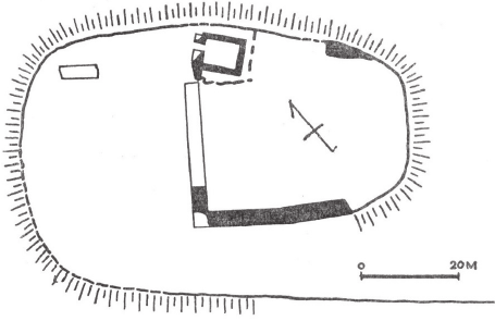
Fig. 3. Plan of Ronov Castle from 1957 (source: Guerquin 1957, 79)
Il. 3. Plan zamku Ronov z 1957 r. (źródło: Guerquin 1957, 79)
18 Milan Sýkora, Paweł Konczewski, Radosław Biel
Results
Based on topographic features and distinct separating
elements (walls, moat, embankments), the castle complex
can be divided into four spatial zones (Fig. 4). Zone I com-
prises the outer foreground of the castle and has the most
ambiguous boundaries. It is located at the southern edge
of the castle area, beyond Zone II, though its extension
into the western valley below the castle remains possible.
Zone II includes the outer fortications, consisting of an
embankment and a moat that surround Zones III and IV.
Zone III is interpreted as the outer bailey, with clearly de-
ned boundaries in the southeastern part of the hill. Zone
IV is considered the original residential core of the castle,
occupying the northwestern portion of the hilltop.
Zone I – foreground
To the south, Zone I is delineated by a steep scarp; to
the north, it is bounded by a moat. Signicant landscape
modications during the construction of House No. 18 in
the 19
th
century partially obliterated the original features in
this area. Part of the moat was lled in, and the associated
embankment was removed, complicating the interpreta-
tion of spatial relations in this sector.
Two roads, likely of medieval origin, provided access
to this zone. The main road approached from the south
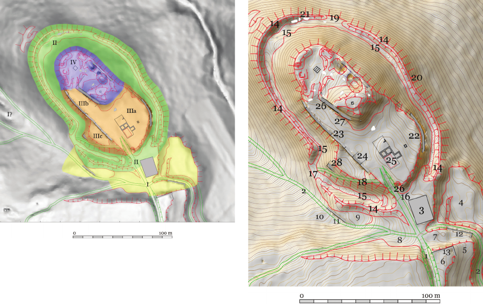
Fig. 4. Delineated functional zones of the complex:
I – outer bailey,
II – outer fortifications,
III – lower ward with subdivisions a, b and c,
IV – upper castle
(elaborated by P. Hlavenka, M. Sýkora, J. Vidman)
Il. 4. Wyróżnione strefy funkcjonalne obiektu:
I – przedpole,
II – zewnętrzne fortyfikacje,
III – przedzamcze z wydzielonymi podstrefami: a, b i c,
IV – zamek
(oprac. P. Hlavenka, M. Sýkora, J. Vidman)
Fig. 5. Plan of the entire castle area (contour interval 25 cm):
1–2 – roads, 3 – House No. 18, 4–10 – early modern terraces,
11–13 – segments of retaining walls, 14 – outer embankment, 15 – moat,
16 – deformed moat section after the construction of the forester’s house,
17 – interruption of the rampart,
18 – former road along the southwestern slope,
19 – interruption or unfinished section of the rampart,
20 – S-shaped bend of the rampart,
21 – rubble of destroyed stone blocks in the moat,
2
2 – eastern perimeter wall of Zone III,
23 – southwestern wall of Zone III,
24 – medieval wall interpreted as a building façade,
25 – foundations of the forester’s house (18
th
–19
th
c.),
26 – quarry, 27 – hypothetical gatehouse,
28 – corner of the perimeter wall or guard tower
(elaborated by P. Hlavenka, M. Sýkora, J. Vidman)
Il. 5. Plan całego obszaru zamkowego (interwał warstwic 25 cm):
1–2 – drogi, 3 – dom nr 18, 4–10 – tarasy nowożytne,
11–13 – fragmenty murów oporowych, 14 – zewnętrzny nasyp, 15 – fosa,
16 – miejsce zniekształceń fosy po budowie leśniczówki,
17 – przerwanie wału,
18 – dawny trakt wzdłuż południowo-zachodniego zbocza,
19 – przerwa lub nieukończony odcinek wału,
20 – esowate wygięcie wału,
21 – gruzowisko zniszczonych bloków kamiennych w fosie,
22 – wschodni mur obwodowy strefy III,
23 – południowo-zachodni mur strefy III,
24 – średniowieczny mur interpetowany jako ściana budynku,
25 – fundament leśniczówki (XVIII–XIX w.), 26 – kamieniołom,
27 – hipotetyczny budynek bramny,
28 – narożnik muru obwodowego lub wieży strażniczej
(oprac. P. Hlavenka, M. Sýkora, J. Vidman)
(Fig. 5: 1), leading from the village and the former manor
of Unter-Ronaw, and likely crossed the moat of Zone II
via a bridge. This route is supported by eld observations
and analysis of terrain morphology, particularly a clearly
dened cut in the slope of the Działoszyn Ridge. A second,
Ronow Castle in Trzciniec – interdisciplinary research on a medieval stronghold at the Czech-Lusatian borderland 19
regionally signicant road (Fig. 5: 2) ran from the south-
east and descended into the western valley, likely as part of
a route between Reichenau and Marienthal.
Within Zone I, to the east of House No. 18 (Fig. 5: 3),
a trapezoidal terrace measuring approximately 40 × 37 m
has been preserved (Fig. 5: 4). Additional terraces (Fig. 5:
5–10) and remnants of retaining walls (Fig. 5: 11–13) ex-
tend along the zone’s western section. While their chronolo-
gy remains uncertain, supercial survey suggests they may
represent early modern modications of the terrain, possi-
bly related to the regulation of road routes. In the western
valley, below the zone, a well is also visible (Fig. 1: 8).
The hill south of the castle and the eastern slope oppo-
site it (Fig. 1: 9) have been proposed as the location of the
siege camp during the 1399 assault. These locations were
suggested based on topographic suitability and accessibil-
ity, though current research has yet to produce evidence
conrming this hypothesis.
Zone II – outer fortifications
Zone II comprises the outer defensive structures of the
castle, consisting of an external embankment (Fig. 5: 14)
and a moat (Fig. 5: 15), which enclosed Zones III and IV,
forming an additional defensive perimeter. The entire sys-
tem takes on an approximately oval form measuring about
160 × 100 m. The embankments reach an elevation be-
tween 270 and 275 m a.s.l., and their course, generally
continuous along the western, northern, and eastern anks,
adapts to the natural topography of the hill. On the south-
eastern side, both moat and embankment rise to about 280
m a.s.l., indicating intentional adaptation of the defences to
terrain features and potential threats. The most substantial
segment of the embankment is preserved along the south-
ern and southeastern portions of the site, underscoring
their heightened defensive importance. In the area of the
former gate (Fig. 6: 16), however, both moat and embank-
ment were signicantly altered due to the construction
of the forester’s house in 1794 and, later, House No. 18
(Fig. 5: 3).
On the southwestern side, the line of the embankment
curves sharply; here, the moat oor drops by 3.5–4 m, and
the embankment itself disappears entirely (Fig. 6: 17). This
interruption is likely related to an old access road (Fig. 5: 18)
leading from the valley up to Zone III via the moat. On
the northern and northeastern sides, the embankment ap-
pears to be interrupted, possibly never constructed in full
or eroded over time (Fig. 5: 19). In the eastern section, near
the junction of Zones III and IV, the embankment follows
a sinuous, S-shaped path (Fig. 5: 20), while the moat bot-
tom rises several meters.
In the northern part of the moat, massive stone blocks
were recorded (Fig. 5: 21), interpreted as collapsed ma-
terial from the upper portions of the castle (Zone IV),
likely resulting from deliberate demolition or destruction
during the 1399 siege. No traces of foundations, mortar,
or masonry rubble were found on the crest of the embank-
ment. Although Karl Christian Eschke (1844) and later au-
thors mention a wall 0.6–1 m in width running along the
embank ment, no material remains conrm its existence.
However, it is plausible that a palisade or so-called parkan,
a type of fortication commonly used in response to the
development of rearms in the late 15
th
century at castles
in Bohemia and Silesia, once existed here; the remnants of
such a structure would not be visible on the surface (Biel
2021).
Zone III – outer bailey
Zone III is interpreted as the outer bailey, whose delin-
eation is clearly dened both by the topography and the
preserved architectural remains. It occupies the southeast-
ern portion of the castle hill and is subdivided into three
distinct sections (Fig. 4). The rst sub-zone, designated
IIIa, comprises a courtyard measuring 52 × 50 m. Adjacent
to its southwestern edge lies the second sub-zone, IIIb,
measuring 16 × 40 m. Below, on the southwestern slope,
sits the trapezoidal sub-zone IIIc, measuring 11 × 44 m.
Together, these form a complex structure suggesting func-
tional dierentiation within the outer bailey.
The eastern boundary of the outer bailey is dened by
a massive curtain wall preserved over a length of 34 m and
up to 5.4 m in height (Fig. 5: 22). The wall runs in a mark-
edly polygonal course, and its facing has been damaged
by later erosion. Its construction consists of medium-sized
stones carefully laid and interspersed with smaller frag-
ments, displaying a tendency toward regular coursing. Five
distinct layers are visible, each between 0.7 and 0.85 m in
height. Three wall openings have been preserved: from left
to right, the rst measures 12 cm in diameter and 1.4 m in
depth; the second is square, 11 × 11 cm, and 1.3 m deep;
and the third, 23 × 22 cm and at least 1.53 m deep, is set
at an oblique angle (~20°) relative to the wall face, likely
serving as a water drain. At this point, the wall’s thickness
exceeds 1.5 m and is probably closer to 2 m. The mortar is
a light ochre-coloured lime binder with a high content of
quartz aggregate and traces of mica.
The southwestern wall (preserved length: 70 m; height
up to 4.5 m) displays evidence of multi-phase construction
(Figs. 5: 23; 6; 7; 8; 8a). Eschke (1844, 270) and Moschkau
(1891) treated it as a monolithic defensive wall; however,
the variation in mortars and construction techniques con-
rms the existence of at least two building phases. In the
medieval walls B and F (Fig. 6), a light ochre lime mortar
with up to 70% washed quartz aggregate (grain size 3 mm
to 1.5 cm) and a minor presence of mica was used. In con-
trast, the early modern walls feature a similar light ochre
lime binder with a higher admixture of river sand and ne,
dark stones, but without mica. The segments labelled A, C,
D, E, and G (Fig. 6) were likely added during 19
th
-centu-
ry adaptations for an inn. Notably, wall E was secondarily
joined to wall F (at the joint), and wall F retains visible cor-
ners at both ends (Fig. 6: 13, 14), suggesting it originally
formed a standalone, enclosed construction element, likely
a building façade (Fig. 5: 24). Only in the later walls (C,
D, E, G) were various niches and technological conduits
identied. These are arranged in two vertical tiers and vary
in size – e.g., 7 × 9 × 65 cm; 6 × 9 × 85 cm; 13 × 10 × 30 cm
– with some set at an angle to the face, likely for drainage
purposes.
20 Milan Sýkora, Paweł Konczewski, Radosław Biel
The largest part of the outer bailey, sub-zone IIIa (52
× 50 m), served as a courtyard. Its surface is nearly level,
with slight slopes to the north-east and south-west. Within
this area is the foundation of an 18
th
-century forester’s
lodge, later converted into a 19
th
-century tavern (Fig. 5: 25).
According to Eschke’s plan (Fig. 2), the southern part of
the courtyard may have housed the gate and bridgehead;
however, extensive alterations due to road construction
and the operation of a small quarry (Fig. 5: 26) now com-
plicate the reconstruction of the medieval building layout.
Sub-zone IIIb (16 × 40 m) may have functioned as
a separate architectural unit. This interpretation hinges on
the analysis of a short southern section of the southwestern
wall of Zone IV (Figs. 5: 26; 7: 1; 8b), which lacks a vis-
ible outer face, suggesting it was later cut back (Fig. 8c).
It is therefore possible that a structure 7.6 m wide abutted
the curtain wall of Zone IV (Figs. 5: 27; 7: 7), crossing the
longitudinal axis of IIIb and functioning as a gatehouse or
a building anking the entrance.
Sub-zone IIIc (11 × 44 m), situated at a lower elevation
than IIIa, may have originally formed a single continuous
space with it. This is suggested by the fact that sections of
the southwestern perimeter wall (Figs. 5: 23; 7: 8), which
today separate IIIa and IIIc, appear to be of early mod-
ern origin. A road leads to IIIc from the west, descending
from the outer fortications along the slope (Fig. 5: 18);
although partly destroyed by later alterations, it is still vis-
ible. Above this road lies the foundation of a rectangular
structure (preserved dimensions: 2.5 × 5.5 m), traditionally
interpreted as a guard tower (Fig. 2: f), though it might also
represent a wall corner (Figs. 5: 28; 8d). The construction
technique indicates a medieval date: the wall was built
from carefully arranged medium-sized stones laid in reg-
ular courses, with a light ochre lime mortar containing
a high proportion (up to 70%) of washed quartz sand (grain
size 3 mm to 1.5 cm), and minimal mica content.
Zone IV – the castle
Zone IV, referred to as the castle, constitutes the prin-
cipal component of the complex, located in the northern
section of the hilltop. This area, with maximum dimen-
sions of 41 × 70 m, features a relatively at topography.
Most of its surface lies at approximately 285 m a.s.l., with
the exception of a raised area up to 3 m higher in the south-
eastern portion (Fig. 7: 9). The zone is enclosed by the
remains of a perimeter wall (Fig. 7: 1–6), which displays
a consistent construction throughout: medium-sized stones
supplemented with smaller ones, laid in courses and bond-
ed with a light ochre lime mortar containing roughly 70%
light quartz sand and a small amount of shale. The layout
suggests that the built environment surrounded an irregu-
lar courtyard. A concrete slab located within the courtyard
(Fig. 7: 10) covers a well described in early accounts. The
only presumed entrance to Zone IV may have been located
where it is today (Fig. 7: 11), in which case the southwest-
ern section of the curtain wall would have had to turn west-
ward. At the hypothetical course of this wall, substantial
rubble remains are still visible.
The best-preserved section of the castle’s curtain wall
is located on the southwestern side, where it measures
2.5 m in width (Fig. 7: 1). The outer face of this segment
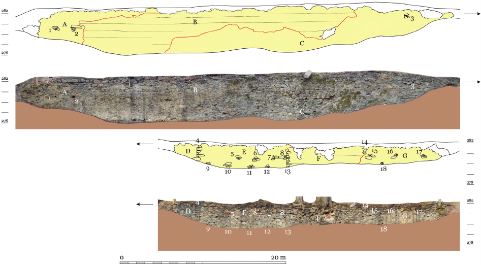
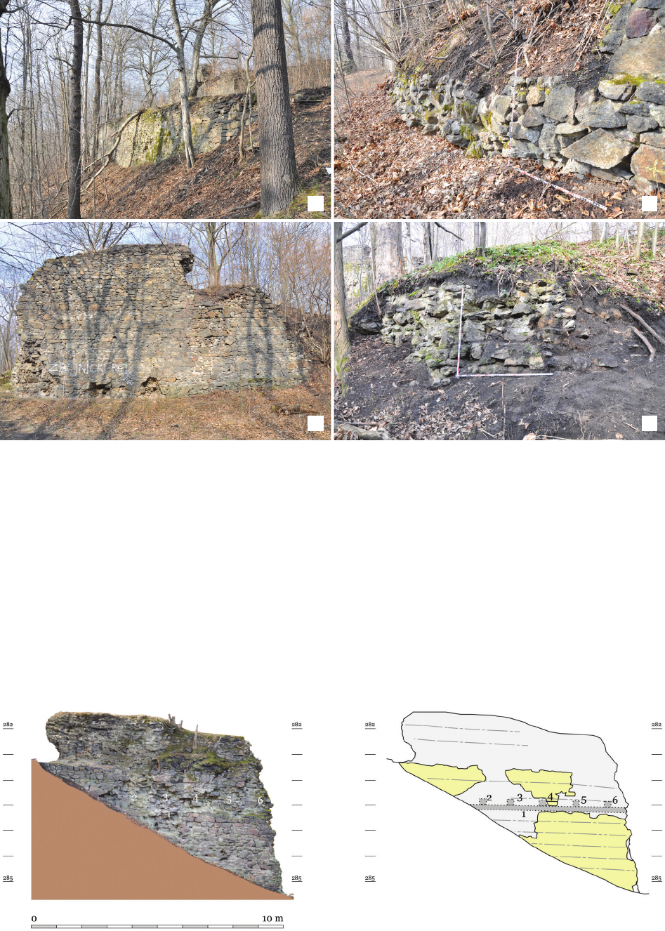
Fig. 6. Photogrammetry and drawing of the southwestern wall of Zone III (external face):
A–G – highlighted wall sections; 1–18 – identified architectural features (elaborated by P. Hlavenka, M. Sýkora)
Il. 6. Fotogrametria i rysunek południowo-zachodniego muru strefy III (lico zewnętrzne):
A–G – wyróżnione odcinki muru; 1–19 – zidentyfikowane elementy architektoniczne (oprac. P. Hlavenka, M. Sýkora)
Ronow Castle in Trzciniec – interdisciplinary research on a medieval stronghold at the Czech-Lusatian borderland 21
Fig. 7. Plan of the castle – Zone IV (contour interval 25 cm):
1–6 – fragments of the perimeter wall, 7 – hypothetical gatehouse,
8 – fragment of the southwestern wall of the lower ward,
9 – elevation with concrete reservoir,
10 – concrete slab covering the well in the castle courtyard,
11 – presumed location of the former entrance,
12 – hypothetical two-storey building,
13 – largest depression interpreted as a cellar,
14 – preserved vaulted cellar,
15 – depression with a partially preserved corridor,
16 – topographic edge, 17 – possible passageway,
18 – erosion trace of the elevation (building?),
19 – remains of an above-ground structure, 20 – rectangular depression
(elaborated by P. Hlavenka, M. Sýkora, J. Vidman)
Il. 7. Plan zamku – strefy IV (interwał warstwic 25 cm):
1–6 – fragmenty muru obwodowego,
7 – hipotetyczny budynek bramny,
8 – fragment południowo-zachodniego muru przedzamcza,
9 – wyniesienie z betonowym zbiornikiem,
10 – betonowa płyta nad studnią na dziedzińcu zamku,
11 – przypuszczalna lokalizacja dawnego wjazdu,
12 – hipotetyczny budynek piętrowy,
13 – największe zagłębienie interpetowane jako piwnica,
14 – zachowana, sklepiona piwnica,
15 – zagłębienie z częściowo zachowanym korytarzem,
16 – krawędź terenowa, 17 – możliwe przejście,
18 – ślad erozji wzniesienia (budynku?),
19 – relikty naziemnego budynku, 20 – prostokątne zagłębienie
(oprac. P. Hlavenka, M. Sýkora, J. Vidman)
is 17.5 m long and partially retains a two-stepped plinth,
projecting 0.18 m at the upper and 0.14 m at the lower level
(Fig. 8b). The inner face is preserved over a length of 9.5 m
(Fig. 9). At an elevation of 287.83 m a.s.l., the lower edge
of a socket for a beam plate was recorded, measuring 20 cm
in height and 30 cm in depth (Fig. 9: 1). Directly above are
ve beam pockets (Fig. 9: 2–6), originally embedded in the
wall. Each is about 30 cm deep, with spacing intervals of
0.84 m, 0.99 m, 1.06 m, and 0.99 m. Although the wall face
is not preserved, the impressions suggest the beams had
a cross-section of approximately 20 × 20 cm. This structure
indicates the presence of a multi-storey building (Fig. 7:
12),
with the upper oor situated at around 288.25 m a.s.l.
Within this wall, mortar joints corresponding to 11 near-
ly horizontal construction layers were observed, sloping
slightly in accordance with the terrain. A short wall frag-
ment, 0.9 m in length, is set perpendicular to this segment
and likely formed part of the same building (Fig. 7: 6).
Three depressions interpreted as cellar remains are lo -
cated in the northeastern and eastern part of Zone IV
(Fig. 7: 13–15). The largest measures 9 × 12 m and con-
tains a at-bottomed area of 2 × 4 m (Fig. 7: 13). Two large
blocks of the perimeter wall, 7 m and 3.3 m long respec-
tively, collapsed into this space, suggesting that the major-
ity of the depression is lled with rubble. From here, a pas-
sage leads into a second preserved cellar measuring 5.4 ×
6.6 m (Fig. 7: 14), which features a barrel-vaulted ceiling
and a ventilation opening in its southwestern side. The
third chamber (8.5 × 7 m), located farthest north (Fig. 7:
15), contains a partially preserved narrow entry corridor
leading towards the central cellar. All three cellars likely
belonged to structures abutting the northeastern section of
the curtain wall. Based on a clearly dened terrain edge
(Fig. 7: 16), it may be inferred that a gap or passage existed
between two parallel wings (Fig. 7: 17). Alternatively, the
layout may have followed an L-shaped plan, with a trans-
versely oriented two-storey building.
In the southeastern portion of Zone IV lies a distinct
raised area, separated from the surrounding terrain by
a steep scarp. At its summit, on a levelled platform, stands
a modern concrete tank (Fig. 7: 9). The front, southeastern
face of the rise may originally have been linear, but now it
forms a concave depression, likely the result of a landslide
or wall collapse (Fig. 7: 18). Notably, if this entire eleva-
tion were composed solely of rubble, for instance from
a collapsed bergfried, it would have completely lled the
underlying depression to the north (Fig. 7: 13), which it did
not. This suggests that the elevated section may conceal
a structure of largely intact masonry. It is unlikely, how-
ever, that it was a cylindrical bergfried, as all of the fallen
wall blocks, including those at the southern base, exhibit
straight faces.
A further building relic, this time above ground, is lo-
cated in the northeastern part of Zone IV near the northern
corner (Fig. 7: 19). This rectangular feature (5 × 9 m) is
surrounded by a small earthen rampart; on the courtyard
side, a 2 m-long, 1.2 m-wide wall segment without a pre-
served face projects from it. The nal feature is a slight
depression along the western edge of the zone (Fig. 7: 20),
rectangular in plan (3 × 4 m). Scattered across the entire
area are numerous fragments of wall masonry, both large
and small, which appear to result from deliberate demoli-
tion rather than natural decay.
Conclusions
The investigation of Ronow Castle conrms the exi s -
tence of an extensive fortication complex with a multi-
com ponent layout comprising at least four clearly dened
functional zones. The developed spatial model remains pre -
liminary in nature, based on non-invasive research meth-
ods, archival queries, and comparative analysis. The spatial
22 Milan Sýkora, Paweł Konczewski, Radosław Biel
Fig. 8. Ronov Castle in 2022:
a – preserved section of the southwestern perimeter wall of Zone IV,
corner near the hypothetical entrance,
b – perimeter wall of Zone IV from the south, at the site of the presumed dismantled gate,
c – tower or corner of Zone III, view from the south-west,
d – southwestern wall of Zone III, view from the south-west
(elaborated by M. Sýkora)
Il. 8. Zamek Ronow w 2022 r.:
a – zachowany odcinek południowo-zachodniego muru obwodowego zamku (strefy IV),
narożnik w pobliżu hipotetycznego wjazdu,
b – mur obwodowy strefy IV od południa, w miejscu hipotetycznej rozebranej bramy,
c – wieża lub narożnik strefy III, ujęcie z południowego zachodu,
d – południowo-zachodni mur strefy III, ujęcie z południowego zachodu
(oprac. M. Sýkora)
Fig. 9. Photogrammetry and drawing of the southwestern wall of Zone IV (internal face): 1–6 – identified architectural features
(elaborated by P. Hlavenka, M. Sýkora, R. Biel)
Il. 9. Fotogrametria i rysunek południowo-zachodniego muru strefy IV (lico wewnętrzne): 1–6 – zidentyfikowane elementy architektoniczne
(oprac. P. Hlavenka, M. Sýkora, R. Biel)
a c
b d
Ronow Castle in Trzciniec – interdisciplinary research on a medieval stronghold at the Czech-Lusatian borderland 23
Acknowledgements
We extend our sincere gratitude to all those involved in the research at
Ronow Castle. We are especially grateful to Pavlína Bína, František Ga-
briel, Lucie Kursová, Paweł Rajski, Pavel Hlavenka, Jaroslav Zastoupil,
and Ivan Peřina, for their invaluable contributions. We also thank the
Forest District of Pieńsk for facilitating access and enabling the eld in-
vestigations.
References
Beránek, Jan, and Petr Macek. “Provádění SHP.” In Metodika stavěbne-
historického Průzkumu, edited by Jan Beránek, Petr Macek. Národní
Památkový Ústav, 2015.
Biel, Radosław. “The functional analysis of the 15
th
century fortication
of the Grodno Castle.” Architectus 86, no. 4 (2021): 29–39. https://
doi.org/10.37190/arc210403.
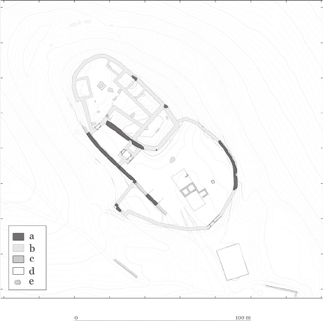
distribution of architectural elements enables the hypothet-
ical recon struc tion of their functions and, to some extent,
their chro nological development (Fig. 10).
The castle (Zone IV), enclosed by a massive perimeter
wall with a clearly dened gate and remnants of interior
buildings, likely constituted the original residential core,
to which additional fortications were subsequently added
in response to the evolving needs of its owners. The layout
of the defensive system suggests that its individual com-
ponents underwent multiple phases of reconstruction. The
conguration of ramparts and ditches points to their phased
development, and parts of the outer circuit (Zone II) may
be associated with late 14
th
-century extensions, potentially
in reaction to the advent of gunpowder weaponry.
A key framework for interpreting the castle’s architec-
tural history is its ownership history. The documented as-
sociation of the castle with the Ronow family in the 1260s,
and its subsequent grant to Anselm of Ronow in the 14
th
century, delineates potential phases of construction and
transformation. The castle’s destruction in 1399 by the
forces of the Lusatian League marks the end of its function
as a seat of power.
The research also enabled the verication of certain
earlier interpretations – some archival data, particularly
concerning measurements and spatial subdivisions, were
corroborated by the current state of preservation. Other
hypotheses, such as the crowning of the outer rampart
with a defensive wall or the existence of a transverse wall
with a tower extending beyond the lower castle’s perime-
ter, were not conrmed. Nor was it possible to denitively
identify the hypothesised siege positions from 1399. The
road network and terrace arrangement are interpreted as
products of early modern redevelopment associated with
changes in regional communication routes.
Summary
The most recent investigations of Ronow Castle in
Trzciniec have signicantly expanded our understanding
of this multi-part defensive complex. The study focused
on the detailed documentation of architectural remains and
their relationship with the surrounding landscape. The dat-
ing and interpretation of certain structural elements still re-
quire further analysis, particularly through targeted archae-
ological sondages (excavations). Although comparative
studies with other regional castles were not the main focus,
Fig. 10. Hypothetical reconstruction of the ground plan of Ronov Castle:
a – preserved medieval walls,
b – reconstructed course of medieval walls,
c – preserved early modern walls, d – contemporary buildings,
e – fragments of destroyed walls
(elaborated by M. Sýkora)
Il. 10. Hipotetyczna rekonstrukcja planu zamku Ronow:
a – zachowane mury średniowieczne,
b – rekonstruowany przebieg murów średniowiecznych,
c – zachowane mury nowożytne, d – współczesne budynki,
e – fragmenty zniszczonych murów
(oprac. M. Sýkora)
they may oer a useful foundation for future research on
Central European fortied architecture.
Ronow Castle remains an important site for future in-
terdisciplinary investigations. Continued work, including
geophysical prospection and intrusive excavation, may
reveal previously unknown aspects of its history and ar-
chitecture, underscoring the value of this historic structure
as evidence of medieval engineering the complex political
developments in the borderlands of what are now Germa-
ny, Poland, and the Czech Republic.
Translated by
Radosław Biel
24 Milan Sýkora, Paweł Konczewski, Radosław Biel
Bláhová, Marie. Staročeská Kronika Tak Řečeného Dalimila. Academia,
1988.
Bobková, Lenka, Tomáš Velička, Mlada Holá, and Jan Zdichynec. Jan
Zhořelecký, třetí syn Karla IV (1370–1396). Casablanca, 2016.
Boguszewicz, Artur. Corona Silesiae: zamki Piastów fürstenberskich na
południowym pograniczu księstwa jaworskiego, świdnickiego i zię-
bickiego do połowy XIV wieku. Wydział Nauk Historycznych i Peda-
gogicznych Uniwersytetu Wrocławskiego Katedra Etnologii i Antro-
pologii Kulturowej, 2010.
Carpzov, Johann Benedict. Annalecta Fastorum Zittaviensium Oder His-
torischer Schauplatz Der Löblichen Alten Sechs-Stadt Des Marg-
grathums Ober-Lausitz Zittau. Bd. 1. Johann Jacob Schoeps, 1716.
Chorowska, Małgorzata. Rezydencje średniowieczne na lsku: zamki,
pałace, wiee mieszkalne. Ocyna Wydawnicza PWr, 2003.
Emler, Josef. Regesta diplomatica nec non epistolaria Bohemiae et Mo-
raviae. Pars II. Annorum 1253–1310. Haase, 1882.
Eschke, Karl Christian. “Beschreibung des Burgstalls zu Rohnau.” Neues
Lausitzisches Magazin, no. 22 (1884): 269–76.
Friedrich, Gustav, ed. Codex diplomaticus et epistolaris regni Bohemiae.
Tomus II (1198–1230). Sumptibus Comitiorum Regni Bohemicae,
1912.
Gabriel, František, Lucie Kracíková, and Ivan Peřina. “Problém dvou
hradů jménem Ronov.” In V kruhu středověkých rodů v Cechách
a také na Slezsku a Lužici: materiály z popularně vědecké konfer-
ence, edited by Bożena Adamczyk-Pogorzelec, Janusz Dziaczko.
Muzeum Regionalne w Lubaniu, 2008.
Guerquin, Bohdan. Zamki ślskie. Wydawnictwo Budownictwo i Archi-
tektura, 1957.
Guerquin, Bohdan. Zamki w Polsce. Arkady, 1974.
Guth, Peter L. “Castles in the Clouds: LiDAR for Historical Study and
Terrain Analysis.” Scientia Militaria 46, no. 1 (2018): 79–95. https://
doi.org/10.5787/46-1-1226.
Hille, Georg. “Chronologisches Verzeichniß der im Rathsarchiv zu Luck-
au in der Niederlausitz bendlichen Urkunden.” Neues Lausitzisches
Magazin, no. 46 (1869): 63–141.
Kajzer, Leszek, Stanisław Kołodziejski, and Jan Salm. Leksykon zamków
w Polsce. Arkady, 2001.
Knothe, Hermann. Geschichte der Dörfer Rohnau, Rosenthal und Scharre,
bei Hirschfelde in der Königl. Sächsischen Oberlausitz. Pahl, 1857.
Konczewski, Paweł, Milan Sýkora, Lucie Kursová, Pavel Hlavenka,
Ja roslav Zastoupil, Ivan Peřina, and Radosław Biel. Sprawozdanie
z nie inwazyjnych badań archeologicznych zamku Ronow w Trzcińcu,
powiat zgorzelecki. Most–Wrocław 2022. [Manuscript in: WUOZ,
Wrocław, Delegatura Jelenia Góra].
Kondracki, Jerzy. Geograa regionalna Polski. PWN, 1998.
Legut-Pintal, Maria, and Paweł Rajski. “Zamek Ronow w Trzcińcu, gm.
Bogatynia.” Published February 10, 2023. Accessed February 10, 2025,
at https://zamki.pwr.edu.pl/trzciniec-gm-bogatynia-zamek-ronow/.
Lehký, Ivan, and Milan Sýkora. Pyšna Sídla Mocných. Hrady a Tvrze
Na Mostecku. Ustav archeologické památkové péče severozápadnich
Čech, 2014.
Menclová, Dobroslava. České Hrady. Díl 2. Odeon, 1972.
Moschkau, Alfred. Führer durch die Oberlausitz: mit besonderer Berück-
sichtigung des Zittauer Gebirges (Oybin, Hochwald, Lausche, Isar-
kamm etc.) und des angrenzenden Böhmens. Senf, 1891.
Panáček, Jaroslav. “Anselm a Předbor z Ronova – ale ze kterého?” Cas-
tellologica bohemica, 19, no. 1 (2020): 103–18.
Pescheck, Christian Adolf. Handbuch der Geschichte von Zittau. Zweiter
Theil. Schöpf, 1837.
Pilch, Józef. Leksykon zabytków architektury Dolnego lska. Arkady,
2005.
Reu, Jeroen De, Gertjan Plets, Geert Verhoeven, Philippe De Smedt,
Machteld Bats, Bart Cherretté, et al. “Towards a Three-Dimensional
Cost-Eective Registration of the Archaeological Heritage.” Jour-
nal of Archaeological Science 40, no. 2 (2013): 1108–21. https://doi.
org/10.1016/j.jas.2012.08.040.
Sedláček, August, ed. Zbytky register králův římských a českých
z let 1361–1480. Česká akademie císaře Frantička Josefa pro vědy,
slovesnost a umění, 1914.
Šebánek, Jindřich, and Sáša Dušková, eds. Codex diplomaticus et episto-
laris regni Bohemiae. Tomi V, Fasciculus 1. Academiae Scientiarum
Bohemoslovacae, 1974.
Šimák, Josef V. Středověká kolonisace v zemích Českých. J. Laichter,
1938.
Sovadina, Miloslav. “Ronovci a Žitava ve 13. a v 1. čtvrtině 14. století.”
Bezděz. Vlastivědný sborník Českolipska, no. 6 (1997): 7–18.
Sovadina, Miloslav. “Rozrod Žitavských Ronovců ve druhé polovině 13.
století.” Bezděz. Vlastivědný sborník Českolipska, no. 7 (1998): 15–34.
Urban, Jan. Lichtenburkové. Vzestupy a pády jednoho panského rodu.
Nakladatelství Lidové noviny, 2003.
Wenzel, Friedrich. “Rohnau.” Die Oberlausitz als besondere Abtheilung
von Sachsens Kirchen – Galerie, no. 14 (1840): 120–22.
Streszczenie
Zamek Ronow w Trzcińcu – interdyscyplinarne badania średniowiecznej warowni na pograniczu czesko-łużyckim
Zamek Ronow w Trzcińcu koło Bogatyni, związany z możnowładczym rodem Ronowców (Ronovci), odgrywał w regionie kluczową rolę politycz-
no-wojskową od XIII do XV w., pozostaje jednak słabo rozpoznany w polskiej literaturze przedmiotu.
W artykule zaprezentowano wyniki interdyscyplinarnych badań przeprowadzonych w 2022 r. Zakres prac obejmował kwerendę archiwalną, kry-
tyczne studium wcześniejszych opracowań oraz analizę reliktów architektonicznych i uwarunkowań krajobrazowych. Zastosowano tradycyjną me-
todologię historyczną w połączeniu z nowoczesnymi technikami dokumentacji przestrzennej (fotogrametria naziemna, lotnicze skanowanie laserowe
LiDAR).
W wyniku przeprowadzonych badań dokonano funkcjonalnego podziału terenu zamkowego na cztery strefy: przedpole, zewnętrzne fortykacje,
przedzamcze oraz zamek właściwy. Potwierdzono ślady wielofazowej rozbudowy założenia, w tym relikty murów obronnych, systemu komunikacyj-
nego oraz piwnic, a ponadto zidentykowano nowe elementy architektoniczne, m.in. dwupiętrową budowlę w niepodpiwniczonej części zamku. Wy-
niki umożliwiły również werykację części wcześniejszych hipotez, dotyczących m.in. konstrukcji umocnień zewnętrznych oraz istnienia rzekomego
muru poprzecznego z wieżą wysuniętą poza przedzamcze. Nie rozstrzygnięto natomiast kwestii szczegółowego rozwarstwienia chronologicznego.
Autorzy artykułu wskazali na potrzebę kontynuacji badań, zwłaszcza z zastosowaniem metod geozycznych i archeologicznych, w celu pełniejszej
rekonstrukcji historii i architektury zamku Ronow.
Słowa kluczowe: średniowiecze, zamek, Górne Łużyce, Ronow, LiDAR